Recent advances in process automation and optimization search technology have made it easier than ever to perform automated design studies and discover innovative solutions. But we still have to define the problem we want to solve and then decide how to represent that problem in our models. These two tasks are sometimes challenging, and they rely heavily on experience and intuition. In this article, as well as some future ones, we will share some of our experience in defining and representing various types of optimization problems. Hopefully you will find some of these techniques useful in your applications.
 A common design scenario is to optimize the number and location of certain design features to satisfy performance goals and requirements. For the sake of discussion, let’s consider a specific example of this type of problem. Suppose we need to attach a cross-member to the rails of an automotive chassis using fasteners, as shown in Figure 1.Our design challenge is to determine the optimal number and location of these fasteners to achieve our goals related to chassis stiffness, durability, mass and cost (for example). While the representation of fasteners in a finite element structural model is not trivial, there are now standard approaches for doing this well. But the model for use in our optimization design study needs to accommodate different numbers and locations of fasteners that can be controlled automatically through the specification of defined parameters – our design variables. Developing a parametric CAD model and an associated finite element model for this situation is certainly possible, but not simple.
In many problems like this, there may be a way to represent the problem without using a parametric CAD model at all. If we can identify ahead of time the possible locations of fasteners, then we can build just one CAD model and one finite element model that contains fasteners at all of these locations. In other words, our model will contain many more fasteners than we want, and we will let the optimizer decide which ones to keep and which ones to eliminate. Let’s discuss how to do this.
The job of a fastener is to transfer load from one structural member to another while maintaining a fixed relative position between the two members. To achieve this task, a fastener must be sufficiently stiff and strong. In the model we discussed above, we purposely included too many fasteners in our model. If we want to eliminate one or more of these fasteners, we can effectively do this by assigning reduced material properties (e.g., very low Young’s modulus) or geometric properties (e.g., very small cross-sectional area) so that they no longer contribute any meaningful stiffness to the system. In other words, those fasteners selected for elimination are assigned properties that make them ineffective load carriers compared to the other fasteners, so it is like they don’t even exist in our model. Thus, by allowing the optimizer to assign either a normal or a reduced stiffness to each fastener during an automated design study, it can determine the optimal number and location of fasteners in the system. Mission accomplished, without a parametric CAD model!
Of course, if you assign a stiffness or cross-sectional area that is too small, you create the risk of causing numerical problems in your model. We suggest you experiment with this to determine the best stiffness reduction strategy, but our experience indicates that a reduction of four to six orders of magnitude works well for many problems.
This strategy works on many types of problems. An example of this is designing the number and location of roof bows in an automotive structure (see Figure 2).
You can control the fidelity of the search by including more or fewer features (locations) in your model. The upper limit on fidelity is controlled by the requirement that features in the model are discrete and not overlapping.
We hope this tip helps you to discover better designs, faster.
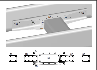
Figure 1. A cross-member is attached to an automotive chassis using fasteners. Extra fasteners are included in the model so that the optimizer can choose which ones to keep and which ones to eliminate in order to best meet the design goals. A fastener in the model can be eliminated by assigning it a very low stiffness.
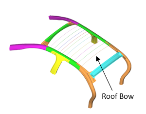
Figure 2. Roof bows in an automotive body help to support the upper structure during a side impact or roll-over crash event. The optimal location of these frame members is difficult to determine because the most relevant loading cases are highly nonlinear and dynamic. If we include many roof bows in our model, then the optimizer can eliminate the unnecessary ones by assigning very low values for the material stiffness, strength and density in those members.